
How intensive deformation roll forming method helps to reduce the length of the machines.
The longer, the better” is what just about anyone will say when you ask about roll-forming machine design.
Having more than enough quantity of roll-forming stations, you can gradually make any kind of profile with no stress, waves and ripples. However, each additional foot of the machine is not only about machine cost and delivery terms, but also rising demands for the workshop space, power requirements, handling weight and lack of mobility.
Intensive method of the roll-forming design helps us to build small machines with better budget, terms and gives a chance to small businesses to do the things that only big guys could afford before.
Below are some engineering examples:
As a sample, a regular 1.5” double standing seam roof panel was used.
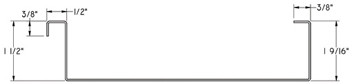
(PIC 1) 1.5” standing seam profile drawing.
To show the difference, rollers were designed for this profile in seven passes with a Regular Roll-Forming (RR) method and an Intensive Deformation (ID) method.
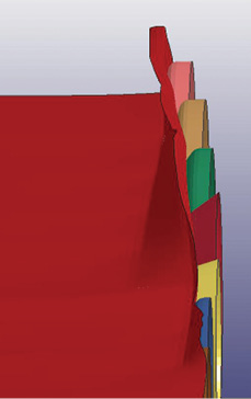
With RR design, bends go successively one by one starting from the edge to the center of the material (please see picture 2).
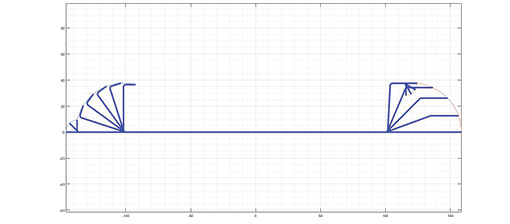
(PIC 2) Flow-forming flower for RR forming design method.
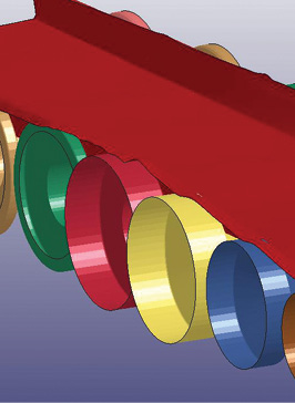
ID method undermined forms several bends on each pass (please see picture 3).
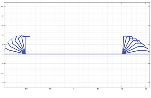
(PIC 3) Flow-forming flower for Intensive Roll-Forming design method.
As raw material we use 24 gauge steel ASTM A653-96.
The tensile strength is 210 MPa, the Poisson’s ratio is 0.3, the yield strength is 350 MPa, the hardening modulus in the plastic region is 587 MPa. Modeling of the deformation process was carried out in the Ls-Dyna program.
Modeling the working tool only simulated the working surface of the calibrated rollers. In this case, the drive has only lower rollers, and the upper ones not propelled. In modeling, the feeding rollers used as first pass with no bands on, therefore eight stands are present in the model.
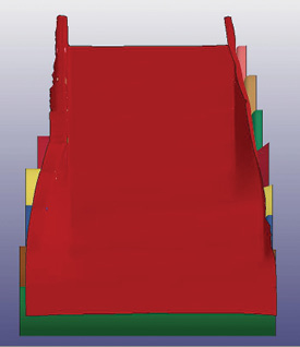
(PIC 4A) General view.
(PIC 4B) Loss of stability of the left edge.
(PIC 4C) Loss of stability of the right edge.
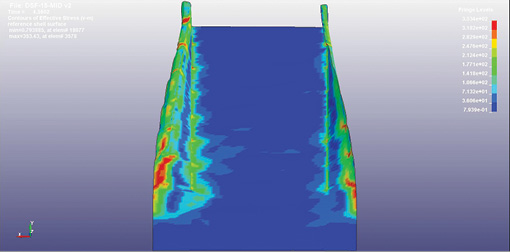
The shape of the material in formed state during the molding process is shown in picture 4a, the upper rollers were hidden. Simulation results demonstrate loss of stability is on both edges of the work piece. Picture 4b shows the formation of ripples on the left edge between four and five passes. Picture 4c demonstrates the formation of a kink at the right edge as work piece goes between six and seven passes.
These pictures show the formed state of material at the process of forming, according to the RR method.
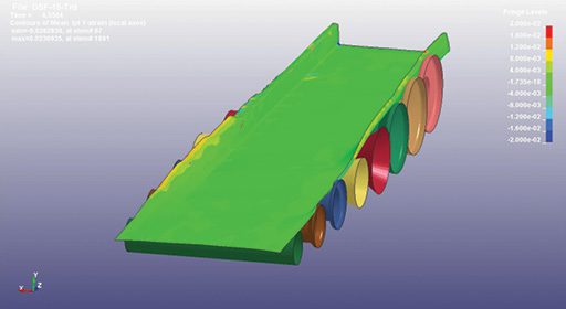
Picture 5 shows the values of equivalent stresses according to the Mises theory. It can be seen from the picture that the largest equivalent stresses occur at the edges of the work piece and its values are 367 MPa, which is higher than the yield point, which is 350 Mpa. That means in places with the greatest values of equivalent stresses will occur plastic deformations, and as a result, edges of the material will be elongated in the longitudinal direction forming ripple defects along the edge shown, displayed in picture 4.
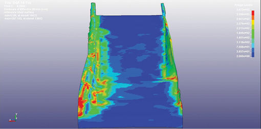
(PIC 5) Equivalent stresses in the work piece during the forming process according to the conventional scheme.
Picture 6 shows the values of longitudinal stresses. You can see on the figure that the greatest longitudinal tensile stresses act in the edges of the work piece as it passes through the second and third passes.
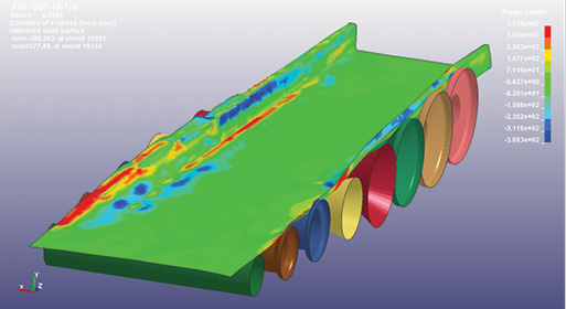
(PIC 6) Longitudinal stresses in the work piece during the forming process according to the RR method.
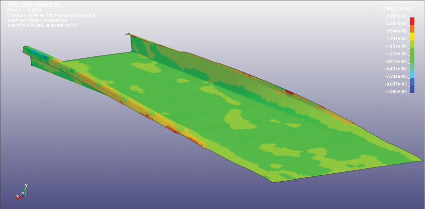
Picture 7 shows the strain values in longitudinal direction. The greatest deformation values reach 2 percent. Such a value is higher than the elastic limit, therefore residual deformations will appear in the work piece, which will subsequently lead to an undesirable deformation of the edge in the form of a ripple.
 (
(
PIC 7) Longitudinal deformations in the work piece during the forming process, according to the RR method.
Picture 8 shows changes of the work piece thickness during the forming process. The picture shows that value of the greatest thinning is about 3 percent. Taking into account the value of the work piece thickness is equal to .0236” (24 gauge or 0.6mm), the absolute value of the thinning is 0.000708”.
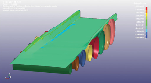
(PIC 8) Changing of the work piece thickness in process of forming, according to the RR Method.
Now the same research was done for the ID roll-forming method. The same thickness, material, profile and desire to get it done well in seven passes.
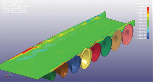
Pictures 9a shows the result of roll forming with ID roll-forming method and there is no edge deformation, ripples or waves seen. And, the other two pictures 9b and 9c, show why it works. The pictures show the work piece in process of roll forming by method of ID.
(PIC) 9 – Overall view.

(PIC) 9b – Right-side edge.
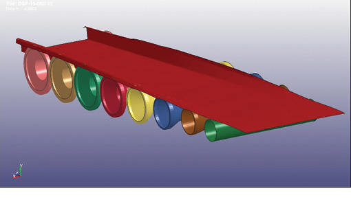
(PIC) 9c – Isometric view.
Picture 10 shows the values of equivalent stresses, the highest value is 353 MPa, which is slightly higher than the elastic limit (350 MPa), and as a result, tensile plastic deformation forces in the edges will be small and most likely, no roll forming defects on the profile edges will be visible.
(PIC 10) Equivalent stresses in a work piece in process of roll forming by the method of intensive deformation.
Picture 11 shows the values of tensile stresses, the highest values reach 367 MPa, which is ~10MPa lower than the traditional method roll forming.
(PIC 11) Longitudinal stresses in a work piece in process of roll forming by the method of intensive deformation.
Pictures 12 and 13 show how the value of the tensile stress of a metal particle located on the left and right edges of the work piece changes, respectively, when the work piece moves through the roll-forming stands. Red color shows stress for roll forming by RR, and blue for ID. Vertical dot-dash lines indicate the position of the axial planes.
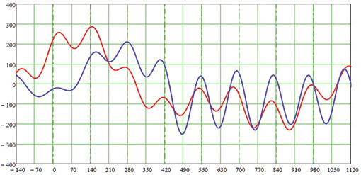
(PIC 12) Stretching stresses in the left edge of the work piece.
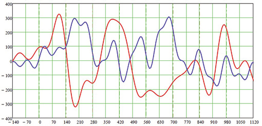
(PIC 13) Stretching stresses in the right edge of the work piece.
The values of longitudinal deformations in a work piece during roll forming by the method of intensive deformation is shown in Picture 14.
The greatest values of deformations are about 0.7 percent, which is about 2 percent less than with roll forming up to traditional method.
The highest change of the work piece thickness during roll forming according to the ID method (Picture 15) is 1.4 percent, which, in terms of the absolute value, is 0.00033”.
These simple mathematical modeling shown depicts that it’s possible to fit good quality roll-forming design in up to 30 percent with less passes using only one method. With the same time, combining several methods, it can be up to 40 percent more efficient.
In conclusion, roll forming design is developing, and there is more interesting solutions that have already come to fruition in the industry and there are for sure more ahead. By following customers’ demands, rational reasons and material development we’ll design better machines—smaller, more energy efficient, faster, more automated and whatever the market demands. There is no reason to be afraid of new technologies; winners are always on the front edge. RF
(PIC 14) Longitudinal deformations in a work piece in the process of roll forming by the method of ID.
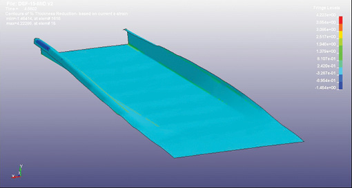
(PIC 15) Change of the thickness of the material in the process of roll forming by the method of ID.
For more information about these techniques, roll forming methods or equipment, please visit www.stangroup.us or contact 570-404-6968.


