From SmartBuild Systems
Abstract
They used a new automation technology from SmartBuild Systems™ (SBS) that allowed them to roll every piece of framing material off a single roll forming machine. These were not ‘dumb’ parts like they could purchase from a typical steel stud manufacturer; each part was precut to length, pre-punched at connection locations, and uniquely labelled. Parts were bundled together and the entire framing package fit on a single truck. At the job site, the pieces were assembled into wall and truss components. They fit together like ‘Tinker Toys’. There was no measuring or marking required to assemble; only to verify dimensions.
In the autumn of 2017 a small startup company in Sundance, Wyoming attempted something new. The company is called Straight Cold Rolling, LLC and they wanted to build a 60’x140′ pole-barn style building using cold formed steel.
There was no saw on the job site (no cutting), only several screw guns. A crew of four untrained laborers was instantly productive because the parts were perfectly made.
How did they do this? Using powerful SmartBuild software, the structural plans were drawn up in the 3D design software. Wall columns and girts were formed into panels. Trusses were designed to a 60 ft clear span. Each wall panel and truss was QC’d in the software for geometry and fit. Then every piece of material was loaded into a data file that fed into special roll-forming machinery. The machine took raw coils of steel and formed them into the pieces specified by the data file.
The results were startling. Cost of raw materials plus the manufacturing labor to roll-form and bundle the parts was competitive with the cost of an equivalent wood building. This was unexpected because the cost of cold formed steel building materials in other market segments usually exceeds the cost of wood materials. An even bigger surprise emerged in the field labor costs. Because the pieces were fabricated to fit together without measuring, marking, or cutting in the field, an untrained crew erected the building as quickly or more quickly than a trained crew could build a wood pole barn.
Framing Design
The building was designed to support up to four independent commercial spaces. The building dimensions were 60 ft by 140 ft and the south wall included (4) 12-ft overhead doors each with an adjacent entry door. Wall height was 16 feet and the roof slope was 4:12. There were no roof overhangs.
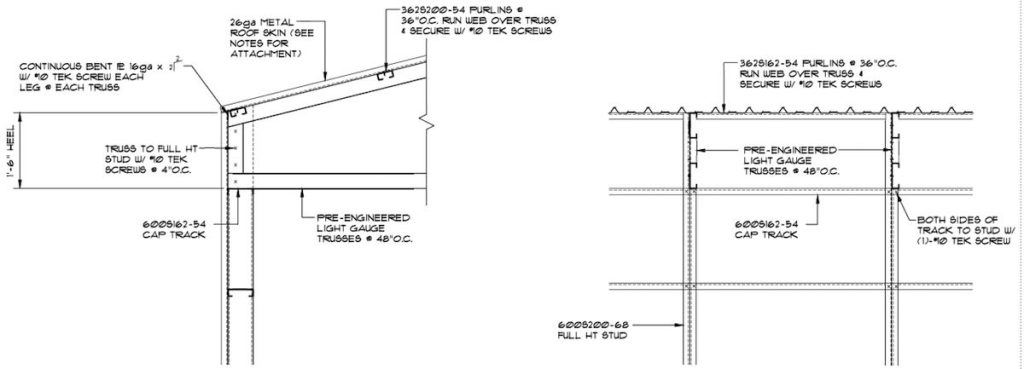
The framing solution included several features to ease the construction process. Wall panels were designed in 4-foot sections. On one end of the panel, the vertical stud (14 gauge) terminated inside the top track; at the other end, the vertical stud (also 14 gauge) extended through the top track an additional 18 inches. As two panels were placed side by side, the 14 gauge end studs were fastened in the field forming an I-shape. The short stud became the bearing point for the truss above (also spaced 4-foot on center), and the long stud provided a connection for the truss (heel height 18 inches) that also formed a moment-resisting connection for the building frame.
Roof purlins were fabricated in 12-foot lengths. The systems used cee-shapes for purlins oriented face down and each purlin had special notching every 4 ft to receive the trusses. This created an automatic spacer for setting the trusses quickly and accurately, increasing the speed of field erection.
Engineering
Structural engineering was completed by Krivonen Associates in Billings, MT. The building was designed under IBC2012 with a ground snow load of 30 psf and ultimate wind speed of 120 mph. An interior shear wall was required to support the 140’ diaphragm in the transverse direction, and diaphragm connection details were included.
The builder desired a concrete floor so this foundation consisted of a 4″ slab with 18″ wide x 24″ deep thickened edge footings using (3) #4 reinforcing bars top and bottom. Wall panels were fastened to the foundation using 5/8″ x 8″ anchors at 32 ioc, and hold-down devices were install at the corners. Since not all buildings require a concrete floor, additional foundation options are currently under investigation, such as a strip footing or perhaps a concrete pier system which the wall columns would stand on, anchored with steel hold-down devices.
Trusses were designed using powerful truss design software and a proprietary truss system called KeyTruss that utilizes standard cee shapes with special notching and piece marking to facilitate fabrication. Trusses were spaced 4 ft on center and beneath each truss was a column built from a back-to-back cee stud. Trusses were designed with a 60-ft clear span and a heel height of 18 inches to form the connection with the wall panel. Trusses were designed with 2-inch flanges, which eliminated the need for any web bracing. Truss chords were 6″ 14 gauge cee shapes (600S200-68) with special notching of the flanges to receive the webs at each joint. Truss webs were 3 5/8″ cee shapes and varied between 18 gauge and 16 gauge (362S200-54 and 362S200-43). Truss purlins were made from 3 5/8” 16 gauge cee shapes (362S200-54) oriented face down with notching to receive the trusses. Purlins were spaced at 36 inches on center.
Columns were formed by joining two 6″ 14 gauge cee shapes (600S200-68) to form an I-section. Columns were spaced 4 ft on center to align with the trusses above. Wider wall panels with wider truss spacings are also possible. The top and bottom tracks of the wall panels were made of 6″ 16 gauge shapes (600T150-54) with dimples that matched the vertical columns. The dimples allowed the tracks and columns to snap together even before screwing off the connection. Wall girts were made of 6″ 18 gauge cee shapes (600S200-43) and had special notching to remove the web and lips where the columns passed through. This detail allowed for a strong material that could also receive the exterior sheathing as well as interior sheathing. Wall girts were spaced at 24 inches on center.
Materials List
The materials were manufactured in Marion, Kansas. Special roll-forming machinery was used to convert raw coils of steel into the smart pieces that formed the building. Every stick for every wall and truss was a highly processed piece with custom marking and notching.
The weight of all materials including walls, girts, truss chords and webs, roof purlins, and permanent bracing added up to 42,000 lbs. Since the pieces can be bundled together in a compact fashion, the entire job fit on one truck and the truck was weighted out, then shipped to the job site in Wyoming.
Construction
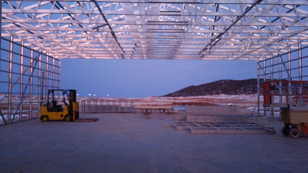
Bundles of materials were delivered to site where the slab had already been poured and prepped. All the wall panels and trusses were assembled on site.
Since all the pieces were cut to length, pre-punched with pilot holes and dimples, and had customized markings, the wall and truss components went together like ‘Tinker Toys’. A crew of four workers who previously had no construction building experience, plus one experienced supervisor, rapidly assembled all the walls and trusses and erected the building.
There was no need to field cut the component parts because each piece had come off the machinery precut to the exact length. Field cutting was only needed for temporary wall braces, etc.
No jigging was required for building trusses. The trusses were self-jigging, using alignment holes and notches in the chords to properly build each truss. Crew members built the first truss using the pilot holes and checked measurements against the construction drawings. The crew squared one end of the truss, then screwed off the rest of the required fasteners. Once the first truss was confirmed, it was used as a template for other trusses, which themselves were first set together using the pilot holes and then screwed off.
Cost Comparison
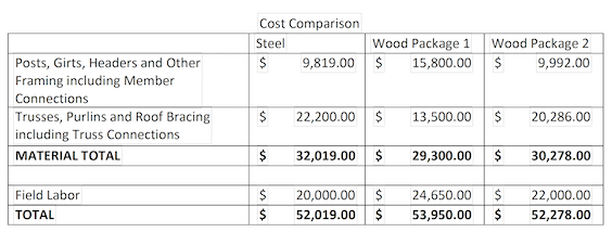
Material costs and field labor costs were tracked throughout the process. Two competitive bids were procured from leading pole barn manufacturers using wood framing. In comparing the costs of the framing, here’s how the numbers stacked up. The steel frame solution generated a combination of labor and materials that is lower than the wood solution.
Conclusion
A 60’x140′ pole barn style building was designed and engineered using a new building methodology. Advanced automation software for building design and truss engineering, combined with special roll forming machinery, created a new building system that went together in the field perfectly, like an Ikea product. The combined cost of materials and field labor was less than a similar wood-framed pole barn.
[Editor’s Note: For more on the emerging cold formed steel framing industry refer to our cover story in October/November 2021 issue of Rollforming Magazine.]


