Weigh your options prior to replacement
How do you know when it is time to replace your roll tooling? It’s a common question posed by roll-former operators. According to Ben Schmidt, Industry Sales Manager for The Bradbury Co., a close look at the end product helps answer that question.
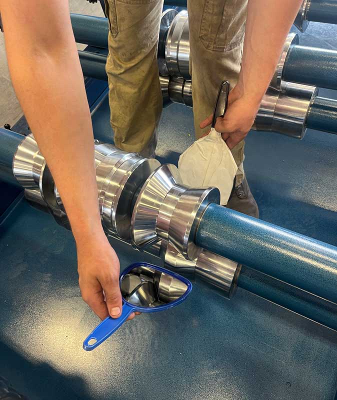
“Typically, the way we diagnose a tooling issue is by looking at what we have coming out the end of the roll former,” he said, placing his focus on the standard 26- to 29-gauge ag panel, 36″ wide with ¾” ribs.
Wavy overlap edge, a cross-bow effect, wider panels, reduced panel features (such as rounded versus sharp major and minor ribs), and low post-cut quality are all likely signs there are problems with the tooling. There are times when those degradations call for immediate tooling replacement and other times when intermediate action can extend the life of your machine.
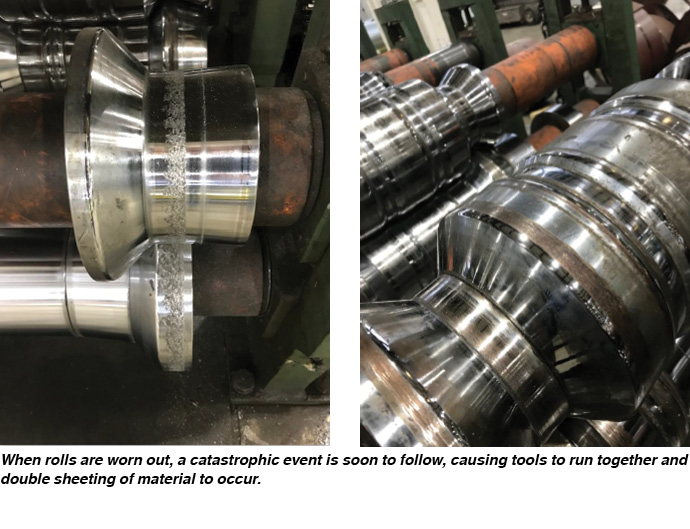
“There are basically two different types of tooling wear,” he explained, “a catastrophic event … and normal wear.”
With a catastrophic event, “something bad happened; you can see it when it happens.”
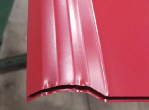
You can also see it in the form of paint damage on the panel. It likely started as a bad adjustment that caused the tools to come together, steel on steel, resulting in pop marks in the paint and paint buildup on the tooling.
Double sheeting is another visible sign of a catastrophic event—when more than one sheet of steel tries to go through your machine at the same time. “When your tools are designed for a maximum of 26 gauge, 0.020 (20 thousandths of an inch), and you send three .015 sheets through, now you have 0.045″ material trying to run through a 0.020″ gap. Worst case, your machine stalls, best case [the panel] gets through the mill but you end up with some worn areas [on your tooling] that will immediately wipe out your bending radii,” Schmidt said.
When a catastrophic event occurs, it is most likely that the tooling needs to be replaced.
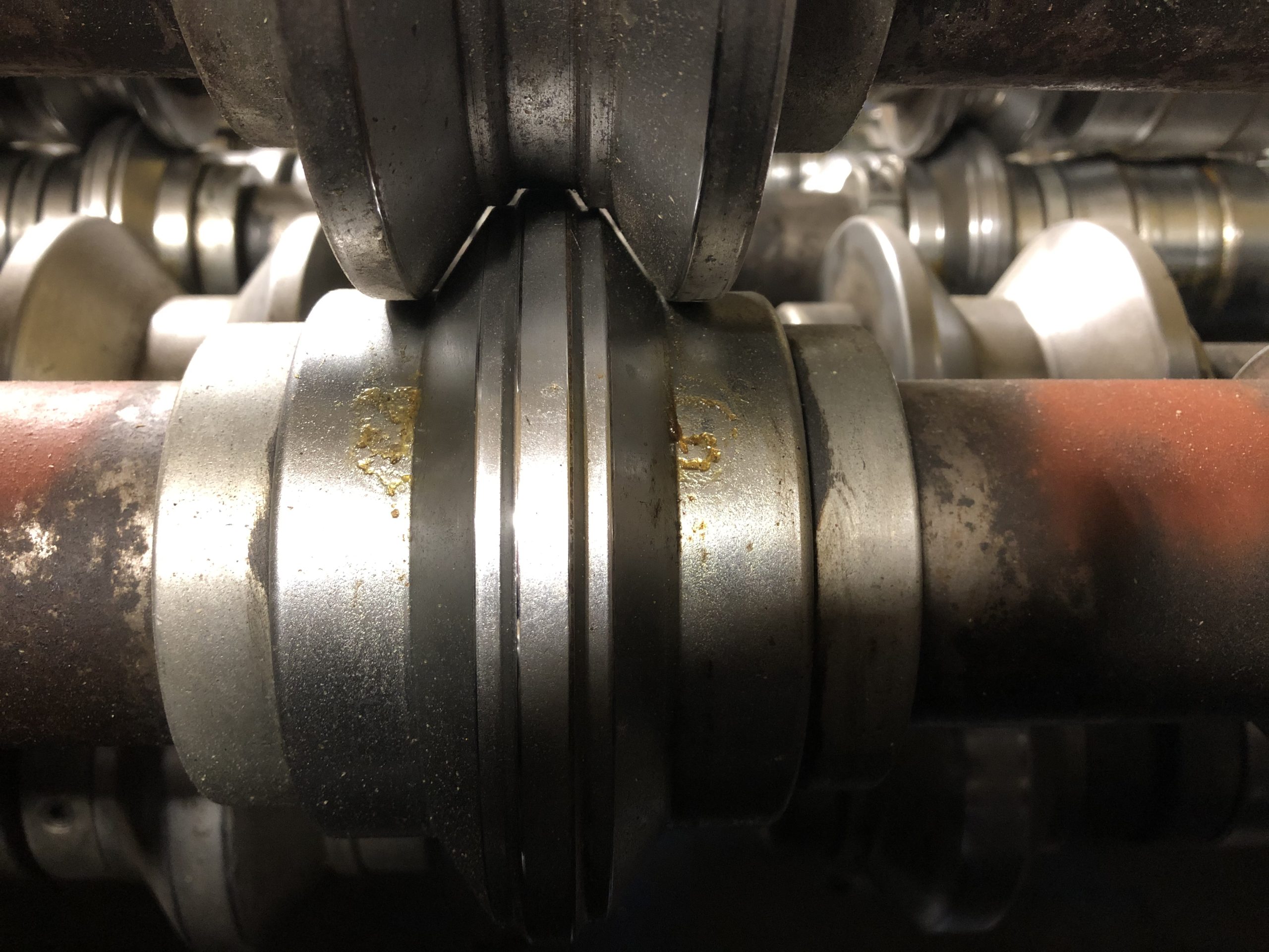
With normal wear, you should notice a gradual decline in the bending radius of your tools. “As you run steel, the bending radii will become lessened, it becomes loose, you can see it in the dies,” Schmidt said. Technicians use radius gauges to check for wear.
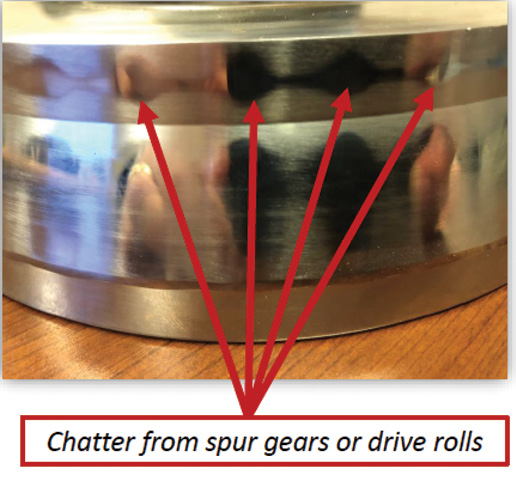
Normal wear can also affect the driveline and create what is called “chatter” in the panel, which is a swirled effect. Chatter can also be caused by chain slack. “The bottom arbor on the roll former is a fixed part—that’s generally what is powered—and when you power the top, normally with a spur gear, if your gears become worn or your driveline becomes worn you get slack,” he said.
The slack affects how material feeds through the machine and affects your machine dies.
“What you will see in the panel when you have chatter, when you look down your minor rib, you’ll see swirl marks going down through it.”
Schmidt noted that the only way to get rid of chatter is to recut or replace the tooling.
Understanding and dealing with normal wear will help avoid quality issues as your tooling ages. Common problems you may detect include:
- • Panel coverage running wide
- • Reduced panel features
- • Wavy edge on overlap
- • Panel flatness control—crossbow affect
- • Large bending radii
- • Degraded quality on post-cut lines
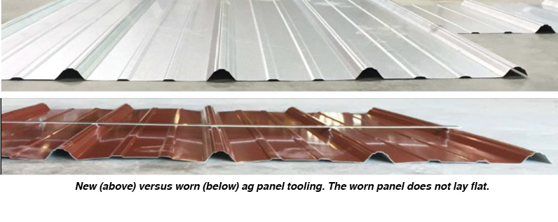
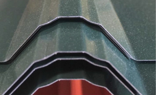
In many cases, the problems are interrelated, such as the case with your panel consistently running wide. A check of your major and minor ribs may detect a reduction in sharpness. Instead of creating sharp edges in the rib ridges, worn tooling is forcing the metal to spread out. “You’re not able to set those bends as much and that extra steel has to go somewhere. That’s what makes your panel wide,” Schmidt said.
“On the majors, instead of having a nice crisp rib, it starts to round. On the minor ribs, worst case it will turn into a half-moon instead of a crisp rib,” Schmidt goes on to explain. “This results in a wider panel because a round bend doesn’t take as much steel as a crisp bend.”
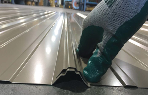
This can be detected visually, but sometimes it is your roofing customer who will notice the problem when they walk across the panel on a job site. “They’ll say it just doesn’t feel as strong. That is because the bends are not set as crisply. The tighter the bends in a panel, the stronger the panel,” Schmidt explained.
Also, as tooling, more specifically the bending radii, starts to wear and loosen, it takes more pressure to create a ¾” rib. “As you come down tighter you start to lose angles, and when you lose angles, that’s where your flatness comes into play,” Schmidt explained, adding: “Once you lose the adjustability you will lose the flatness control on your panel.”
Overlap control determines how weathertight a panel will be. If a panel has a wavy edge it will not provide a tight lap. “To most folks in this business, the lap is just about everything,” Schmidt said. “If you don’t have a tight lap, it’s not a weathertight lap.”
For installers, getting a tight lap is challenging if the ribs are not consistent on the panel currently being installed as well as the panel on which it is being overlapped.
Lastly, if you notice deterioration in your post-cut it is most likely the tooling. “The cut-off die is not very forgiving,” Schmidt noted. “What’s going to give is the 29-gauge panel, not the cutoff die set. This also applies if we’re running precut and chopping down for 2′ panels, you’ll still see some deprivation.”
Solutions Other Than Replacement
The best-case scenario is that you can repair your existing machine rather than replacing the tooling. The first repair solution involves calibration.
Calibration: “When you calibrate a machine, or gauge it, you’ll be setting your vertical clearances, your horizontal clearances, then you’ll want to set your pass-to-pass settings to make sure it aligns throughout,” Schmidt instructed.
Vertical and Horizontal Tooling Clearances: The vertical tooling clearance is the gap between the upper and lower rolls at the farthest point on the inboard (drive side) and outboard (operator side) of the tool for each pass and at points along the flattest sections of the rolls where you have upper and lower mating rolls. Tooling should be initially calibrated for the maximum material thickness for which the tooling was designed.
To calibrate the vertical tooling clearance, you will first identify the maximum designed material thickness, and then adjust the upper arbor so that the maximum material feeler gauge goes between the upper and lower rolls with a slight drag to it. Check the inboard and outboard locations.
Pass-to-Pass Alignment: Roll tooling that has been inspected and calibrated within each individual tooling pass needs to be checked for alignment from tooling pass to tooling pass. First, identify the common spacer/roll width sizes beginning from the inboard side on a series of concurrent passes of tooling. Next, assure that the gap on the precision straight edge does not exceed 0.010 of an inch from pass to pass. Measure with a feeler gauge for accuracy. Note that minor rib passes typically require less gap.
As Schmidt noted, “Engineers design in a perfect world, so you want to make sure the gaps are the same on each piece of tooling.” Proper tooling assures your panel is not snaking through the machine tight on one side and loose on another, causing panel distortions.
That Didn’t Work—Now What?
If calibration does not solve your quality issues, three options are left: retracing or recutting the tooling, partial tooling replacement, or complete replacement.
Recutting: When you have tools recut, all the tools and spacers are removed from the machine, sent to the factory, and stripped, retraced, re-profiled, re-chromed, inspected, and profile tested. The result will be a like-new profile, with shrinkage of the profile at about 0.070 of an inch.
The advantages to a recut include reduced cost—about 50% the investment of a new set—and reduced lead time of about 50%.
One of the disadvantages, however, is the uncertainty. “There is a bit of a risk,” Schmidt said. “You don’t know for sure if those rolls are going to clean up. If you take 0.070 of an inch off, but the tooling is worn extremely, or there happens to be some damage in there somewhere, that means we would have to take more off than the 0.070 or replace the damaged tooling.”
Cutting down more than the 0.070 of an inch is a slippery slope because it could affect your machine’s driveline. “Top arbors are powered from lower arbors with spur gears,” Schmidt said. “If the tooling outside diameters are decreased too much the spur gears will bottom, which prevents the tooling from achieving the proper material gap. To correct the problem additional is incurred due to replacing the top spur gears.”
Yet another disadvantage is restriction on modification once a recut is made. “Your substrate changes, your market changes … and that tooling is already designed, you don’t have the ability to modify it very much,” he said.
Partial Tooling: Partial tooling replacement is a frequent request by customers who have lost minor rib definition or want to restore panel flatness by replacing their overform passes. It is less expensive—about 25% the cost of a new set—with less lead time of 4-6 weeks.
Unfortunately, there is no guarantee that new tooling intermixed with existing tooling will provide you with “like-new” conditions. Again, you will have limited design changes and working with someone other than the original equipment manager (OEM) could complicate getting an accurate estimate.
Complete Tooling Replacement: In the case of a complete replacement of the tooling, all tooling and spacers are replaced. In the end, you will have new tooling and you will have the design flexibility to incorporate changes when the market changes. It is also less risky to source from a non-OEM vendor.
It does require a substantial capital investment, however, and behooves the owner to take a close look at the entire mill system. “If the tool set is worn out, the roll former is probably worn out too,” Schmidt said. “The worst thing you can do is put a brand-new set of tooling on a mill that needs help. Typically, when we recommend a roll-former rebuild, we are going to address the stand bearings, the adjustment assemblies, and the driveline.”
Here is a list of what you will want to do in preparation for your new tooling:
- • Replace roll former stand bearings
- • Replace roll former adjustment assemblies
- • Inspect sprockets, chain, spur gears, and drive rolls
- • Inspect arbors for keyway wear
Continue to use preventative maintenance to ensure a long life and product quality from your machine.
Final thoughts
Roll formers are built to last many years, and unless you experience a catastrophic event with an older machine, you probably won’t see a sudden change in how it works or in the quality of products it produces. “The challenge is, none of this happens overnight,” Schmidt said. “As you run it, it’s difficult to see. It’s like my house; I know my paint is fading, but it’s a gradual decline.”

The solution is having a routine schedule of inspections and maintenance. For roll formers, the name of the game is uniformity, and it is best to keep an eye on the uniformity of your quality to catch its decline first before your customer does. RF
Editor’s Note: This information was provided by Ben Schmidt, The Bradbury Group, in an education session at the 2019 Construction Rollforming Show (CRS). Watch for future updates on education sessions at the 2020 CRS in Cincinnati, Ohio, Dec. 10-11, in Rollforming Magazine. For more information from the Bradbury Group visit www.bradburygroup.com
Originally published as “Is It Time for New Roll Tooling?” Summer 2020 issue Rollforming Magazine.


